
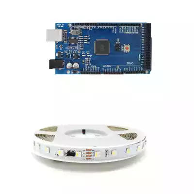
To connect addressable LED strips to Arduino, you will need to use a few jumper wires.
Addressable LED strips have three terminals: two for power (VCC and GND) and one for data (DIN).
1) Connect the positive lead of the LED strip (VCC) to the 5V pin on the Arduino.
2)Then connect the ground lead of the LED strip (GND) to a ground pin on the Arduino.
3)Finally, connect the data lead of the LED strip (DIN) to a digital pin on the Arduino.
Once everything is connected, you will be able to control the LED strip using Arduino code.
1. Control addressable led strip with Arduino
Addressable LED strips are a great way to add special effects to your projects. By chaining together multiple LEDs, you can create complex patterns and animations that would be difficult to achieve with individual LEDs. And because each LED is addressable, you can control each one independently, making it easy to create sophisticated lighting effects.
To control an addressable LED strip with Arduino, you’ll need to use a special type of LED strip known as a WS2812B. These types of LED strips have built-in drivers that allow you to control each individual LED by sending data over a single wire. You can daisy-chain multiple WS2812B strips together to create longer segments, and you can even chain multiple strips together to create larger arrays. While WS2812B strips are more expensive than regular LED strips, they are well worth the extra cost for their added flexibility.
2. Connect the strip to a power supply
Before connecting the LED strip to a power supply, make sure that the voltage and current rating of the power supply is compatible with the strip. Most LED strips operate on 12 volts, so a 12-volt power supply is typically sufficient.
To connect the LED strip to a power supply, first solder two wires to the power supply’s + and – terminals. Then, solder the other end of each wire to the + and – terminals on the LED strip. Finally, plug the power supply into an outlet and flip the switch to turn on the power. The LED strip should now be fully operational.

3. Download and install the Arduino software
In order to get started with Arduino, you will need to download and install the Arduino software. This software is available for free from the Arduino website. Once you have downloaded the software, you will need to unzip it and open the folder. Inside the folder, there will be an application file called Arduino. You will need to double-click on this file in order to launch the software. Once the Arduino software is open, you will be able to connect your Arduino board and start programming.
4. Connect the strip to your computer
The next step is to connect the strip to your computer. First, find an open USB port on your computer. Then, take the end of the strip with the USB connector and plug it into the USB port. The other end of the strip will have a series of bare wires. These wires will need to be connected to the pins on your breadboard. Once everything is plugged in, you should see a series of red, green, and blue LEDs lighting up. If not, check your connections and make sure that the strip is properly plugged into both the breadboard and the USB port. With everything hooked up, you’re now ready to start writing code to control the LED strip.
5. Upload the code to your Arduino board
Arduino boards are able to read inputs – light on a sensor, a finger on a button, or a Twitter message – and turn it into an output – activating a motor, turning on an LED, publishing something online. You can tell your board what to do by sending a set of instructions to the microcontroller on the board. These instructions are known as a sketch. To create your own sketch, you’ll use the Arduino programming language (based on Wiring) and the Arduino Software (IDE), which runs on your computer. Once you’ve created your sketch, you need to upload it to the microcontroller on your Arduino board.
There are two ways to upload your sketches: using the Arduino IDE or using the ArduinoLoader application. With either method, you’ll need to connect your Arduino board to your computer using a USB cable. The Arduino IDE is a cross-platform application that runs on Windows, Mac OS X, and Linux. It includes a code editor with syntax highlighting and autocompletion, and lets you choose from a variety of different Arduino boards and accessories when you upload your sketches. The ArduinoLoader is a standalone application that only runs on Windows. It doesn’t have as many features as the IDE, but it’s less complicated to use if you just want to upload a sketch to your board.
Once you’ve chosen your method, follow the instructions below to upload your sketches.

Arduino IDE
1. Open the Arduino IDE and click the “File” menu.
2. Click “Open” and navigate to the location of your sketch.
3. Click the “Upload” button.
4. Wait a few seconds for the sketch to upload.
5. Once the sketch has been uploaded, you can open the Serial Monitor from the “Tools” menu to see any output from your sketch.

Arduino Loader
1. Connect your Arduino board to your computer using a USB cable.
2. Download the ArduinoLoader application and unzip it.
3. Run the ArduinoLoader.exe file.
4. Click the “Browse” button and navigate to the location of your sketch.
5. Click the “Upload” button.
6. Wait a few seconds for the sketch to upload.
7. Once the sketch has been uploaded, you can open the Serial Monitor from the “Tools” menu to see any output from your sketch.
8. If you want to upload a new sketch, click the “New” button and repeat steps 4-7.
Now that you know how to upload sketches, let’s take a look at how to create one.

Creating a Sketch
The Arduino IDE comes with a set of standard libraries that allow you to control the board’s pins, interact with the Serial port, and more. You can also install additional libraries that add support for new devices and features. To get started, we’ll create a sketch that turns on an LED when you press a button.
1. Connect an LED to pin 13 of your Arduino board.
2. Connect a pushbutton to pin 2 of your Arduino board.
3. Open the Arduino IDE and create a new sketch (File > New).
4. Copy and paste the following code into the editor window:
void setup() {
// Set the button as an input
pinMode(2, INPUT);
}
void loop() {
// If the button is pressed, turn on the LED
if (digitalRead(2) == HIGH) {
digitalWrite(13, HIGH);
}
// Otherwise, turn off the LED
else {
digitalWrite(13, LOW);
}
}
5. Click the “Upload” button to upload the sketch to your board.
6. Once the sketch has been uploaded, press the button to turn on the LED. Press it again to turn off the LED.
This is a very simple sketch, but it demonstrates how easy it is to control the pins on your Arduino board using the IDE. In the next section, we’ll take a closer look at the different types of sketches you can create.

Types of Sketches
There are three main types of sketches:
1. Basic sketches: These are the simplest type of sketch, and they only require the Arduino IDE. You can use the built-in libraries to control the pins on your board, interact with the Serial port, and more.
2. Library sketches: These sketches use one or more additional libraries in addition to the built-in libraries. Libraries are collections of code that add support for new devices and features. Many popular sensors and modules have Arduino libraries available.
3. Core sketches: These sketches require the Arduino Core, which is a set of files that add support for the ATmega328p microcontroller (the chip used on the Arduino Uno). The Arduino Core is only necessary if you’re using a board that doesn’t use the ATmega328p, such as the Arduino Mega.
Now that you know the basics of how to create and upload sketches, let’s take a look at some of the more advanced features of the Arduino IDE.
Advanced Features
The Arduino IDE comes with a number of advanced features that can be used to improve your sketches.
1. Code completion: This feature helps you write sketches faster by automatically completing code for you. For example, if you type “pinMode(“, the IDE will automatically insert the closing parenthesis and semicolon.
2. Syntax highlighting: This feature makes your code easier to read by color-coding different elements. For example, keywords are usually colored blue, and comments are usually colored green.
3. Code formatting: This feature formats your code so that it is easy to read. For example, it will add indentations automatically.
4. Error checking: This feature checks your code for errors and highlights them in the editor window.
5. Serial Monitor: This feature allows you to interact with your sketch using the Serial port. You can use it to send data to your sketch, or receive data from your sketch.
To learn more about these features, and how to use them, check out the Arduino IDE Tutorial.
In this guide, you’ve learned the basics of how to choose the right addressable LED strip for your project. You’ve also learned how to create and upload sketches to your Arduino board using the IDE. Now that you know the basics, you’re ready to start creating your own projects!
6. Test your code
Before you can deploy your Arduino code, it is important to test it to ensure that it is functioning correctly. The best way to do this is to use a simulator. This will allow you to test your code without needing to connect to an actual Arduino board. There are a number of different simulators available, so be sure to choose one that is compatible with your operating system. Once you have installed the simulator, open your code in the Arduino IDE and select the “simulate” option. This will launch the simulator and allow you to run your code. Be sure to pay close attention to the output in the simulator, as this will help you identify any errors in your code. With a little bit of testing, you can be confident that your code is ready to deploy on an actual Arduino board.
7. Deploy your code
After you’ve tested your code and verified that it is working correctly, it’s time to deploy it on an actual Arduino board. To do this, connect your Arduino board to your computer using a USB cable. Then, open your code in the Arduino IDE and select the “upload” option. This will compile your code and upload it to the board. Once the code has been uploaded, you can disconnect the USB cable and your code will continue to run on the board.
How do you control addressable LED strips?
Addressable LED strips are a great way to add dynamic lighting to any space. But how do you control them? Here are a few tips:
First, you’ll need a controller. This can be a standalone unit, or it can be integrated into a larger lighting system. Once you have your controller, you’ll need to connect it to your LED strip. This is usually done via a data cable. Next, you’ll need to program your controller. This will involve creating an animation or pattern that you want your LEDs to display. Finally, you’ll need to power on your controller and enjoy the show!
There are a few different ways to control addressable LED strips, such as ws2811 ws2815 ws2812b strips. One way is to use an offline controller, such as the K-1000c controller or the K-8000c controller. With these controllers, you will need to do animation to an SD card with LEDedit software. Another way to control addressable LED strips is by using an online controller, such as the Madrix controller. With this type of controller, you will need to connect it to a computer and use Madrix software for online control. Whichever method you choose, you will be able to easily control your addressable LED strips.
Can you cut addressable RGB strips?
Addressable RGB (light emitting diode) strips are a great way to add Accent lighting to your home. Because each LED is individually addressable, you can create amazing visual effects. And, since they’re strips, they’re very easy to install. But one question we often get is: can you cut addressable RGB strips?
The answer is yes! In fact, it’s very easy to do. Most addressable RGB strips have cut lines every few inches, so you can simply use a sharp knife or scissors to cut the strip to the desired length. Just be careful not to damage the LEDs or the circuitry. Once you’ve cut the strip, you can just connect it to the controller and enjoy your new lighting!
How do LED strip lights turn corners?
Turning a corner with an LED strip light is easy if you have the proper tools and instructions.
First, you will need to purchase an LED light strip that is specifically made for turning corners. These strips are typically thinner and more flexible than traditional LED strips, making them easier to maneuver. Once you have the strip, simply adhere it to the desired area on the wall or ceiling, making sure that the strip is tight against the surface.
Then, use a sharp knife to carefully cut along the edge of the strip, following the contour of the corner. Once the strip is cut, you can then peel it away from the wall and apply it to the adjacent surface. When done correctly, this method will result in a seamless transition between surfaces and a professional-looking finish.
How do you connect addressable LEDs
To connect an addressable LED, you will need three things:
a controller,
an LED driver,
Addressable LED Strip, such as ws2812b Addressable LED Strip, ws2815 Addressable LED Strip, ws2813 led strip light, APA102C LED Strip Light, DMX led strip light.
The controller will be used to send data to the LED driver, which will then control the brightness and color of the LED. The addressable LED will have a data input and a data output. The data input will be connected to the microcontroller, and the data output will be connected to the LED driver. You will also need to connect a power supply to the LED driver. This will provide power to the LEDs.
Conclusion
In order to connect addressable LED strips to Arduino, you will need a few items. The first is an addressable LED strip. You can get these from many different online retailers or hardware stores. The second item you will need is an Arduino board. These are also available from many different online retailers or hardware stores. Finally, you will need some type of connector cable in order to attach the LED strip to the Arduino board. You can find these at most electronic stores or online retailers as well. If you have all of these items, then connecting the LED strip to your Arduino board should be a breeze! Contact MSH LED Team for more support on how to connect your addressable LED strips and Arduino boards together!
